Logic Circuit Editor
Creating a custom logic gates diagram editor with a professional diagramming library
Logic circuits are used in computers to perform a complex logical operation by chaining logic gates. Clear visualization of a logic circuit makes it easy for the viewer to recognize and understand the relationships between the logic gates quickly. With a comprehensive editor, you can quickly and easily create and expand a circuit interactively.
Logic circuit editors and simulators are mainly used for integrated circuit design and teaching. They help chip designers plan schemas for logic circuits as well as verify their correctness through simulation. In academic backgrounds, teachers and students work with editors to interactively demonstrate and learn how logic circuits work. In both use cases, specialized editors make the handling of easier and provide a deeper understanding of complex logic circuits.
Editor Features
Logic circuit editors allow the user to connect basic logic gates to more complex circuits. Logic gates are usually
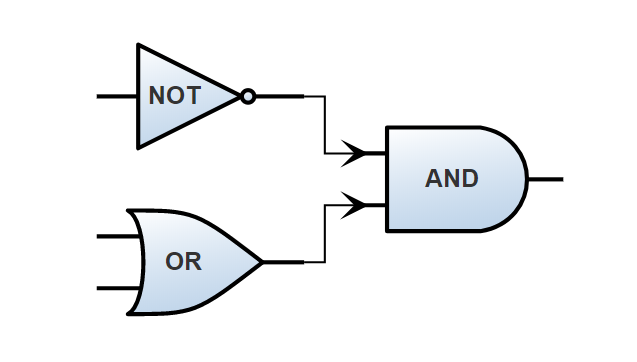
represented by shapes with variable numbers of inputs and outputs. The logic function a gate represents (such as AND
or NOT) is usually denoted by different shapes and symbols or words on them (e.g. “&” for AND).
The connections or wires between gates are represented by lines that are usually drawn orthogonally, so there are only horizontal and vertical lines. Sometimes, arrows indicate the direction of a wire.

The user can usually add new gates to the circuit by dragging them from a palette onto the canvas. New wires are usually created by dragging from the output of a gate to the input of another gate. Smart editors automatically create new connections orthogonally and also disallow connecting two inputs or two outputs.
This sample application features a simple online logic circuit editor built with yFiles for HTML, a specialized diagramming library.
Drawing Logic Circuits
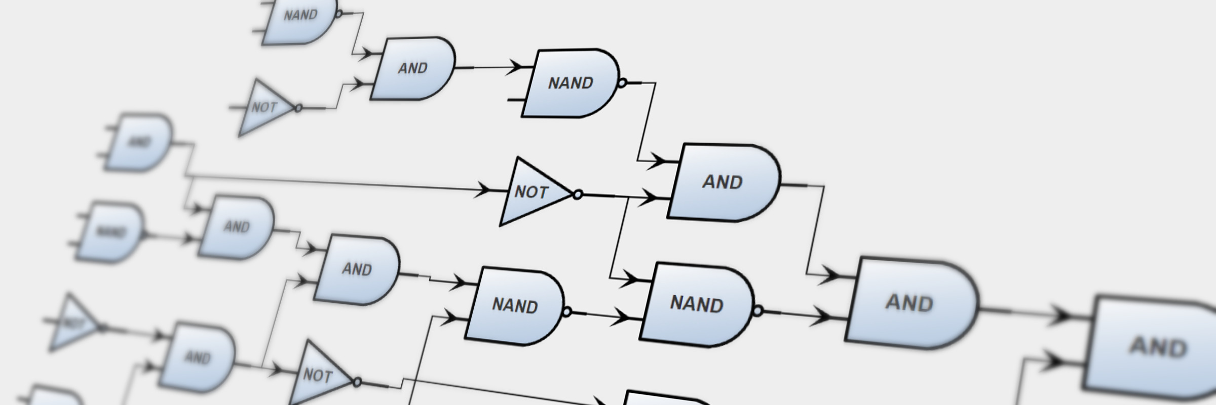
Drawing diagrams such as logic circuits in a readable way is a complicated task. While visualizing the single gates and the wires are relatively simple, arranging the elements on the canvas is challenging: The gates need to be arranged so that the distance between connected gates is minimal, and the wires connecting them have a minimum amount of crossings. Since calculating such layouts is not easy, many logic circuit editors leave this part to the user.
With the growing size and complexity of the circuits, manual layout soon becomes very time-consuming. A logic circuit editor that is capable of automatically arranging the gates and wires automatically can save the user a lot of time and effort. Another benefit of an automatic layout is that, for larger diagrams, the results are often more clear and readable.
When calculating the layout of a logic circuit automatically, there are two options. Either, only the paths of the wires are calculated while the positions of the gates are left untouched, or both the gate positions as well as the wire paths are calculated. The first approach has the advantage that the user’s mental map of the diagram is preserved: if the automatic layout in the second approach arranges the diagram entirely different than it was before, the user loses track of where the single gates and wires are. They have to analyze the graph from scratch again visually. Incremental layout algorithms try to solve this problem by moving gates and wires as little as possible and thus preserving the user’s mental map.
The sample application was built with yFiles for HTML, a commercial diagramming library that features excellent graph visualization and unequaled automatic diagram layout. The example application features a drag and drop palette that provides the user with a set of logic gates. They can create wires by dragging from a gate’s output to another gate’s input or vice versa. The application automatically draws the wires in an orthogonal fashion. Users can run an automatic layout by pressing the layout button and can choose if both gates and wires shall be arranged or only the wires. The example application makes use of yFiles’ Hierarchic Layout.
Example and Source Code
yFiles comes with a Logic Circuit Editor Sample Application. This example demonstrates how yFiles for HTML can be used for the visualization of a digital system consisted of logic gates.
The source code of the Logic Circuit Editor Sample Application is part of all yFiles packages and available on the yWorks GitHub repository:
Draw Logic Circuits in Your Own Application
Test the yFiles for HTML diagramming library with a fully functional trial package. To display logic circuits in your own application, start with the Logic Circuit Editor Sample Application that is part of the yFiles package. It’s not only a showcase application but also provides best-practice source code that you can re-use in your own project.
yFiles makes it easy to customize all aspects of this application, for example include your own styling, change the user interaction, or load the data from your own data source. Features like the node visualizations and the specialized automatic layout are separate components that work in any yFiles-based project.
-
Download the trial version of yFiles for HTML for your target platform at the yWorks Customer Center.
-
Navigate to the source directory of the Logic Circuit Editor Sample Application.
-
Explore the sample application’s features and
-
adjust its source code to match your requirements or
-
copy the source code of the features you like to your own project.
-

