Software Documentation With UML Diagrams
Advantages of graphical software documentation and how to leverage UML diagrams in the development process
Unified Modeling Language (UML) diagrams provide a standardized graphical representation for software systems.
The overall software structure is the backbone of each system and has a significant impact on software quality and its maintainability. Any new feature or change needs to be integrated into this structure without interfering or breaking other existing parts of the system. Particularly in agile software development processes, it helps to keep the overall system structure well organized.
Why use a UML diagram?
A standardized format like UML brings everyone on the same page and simplifies feature discussions in the team.
In addition to representing the structure of a system, UML is also used to depict behavioral aspects and interactions within a system. This includes modeling the flow of operations and transitions of data between different components or entities.
What are the elements of a UML Class Diagram?
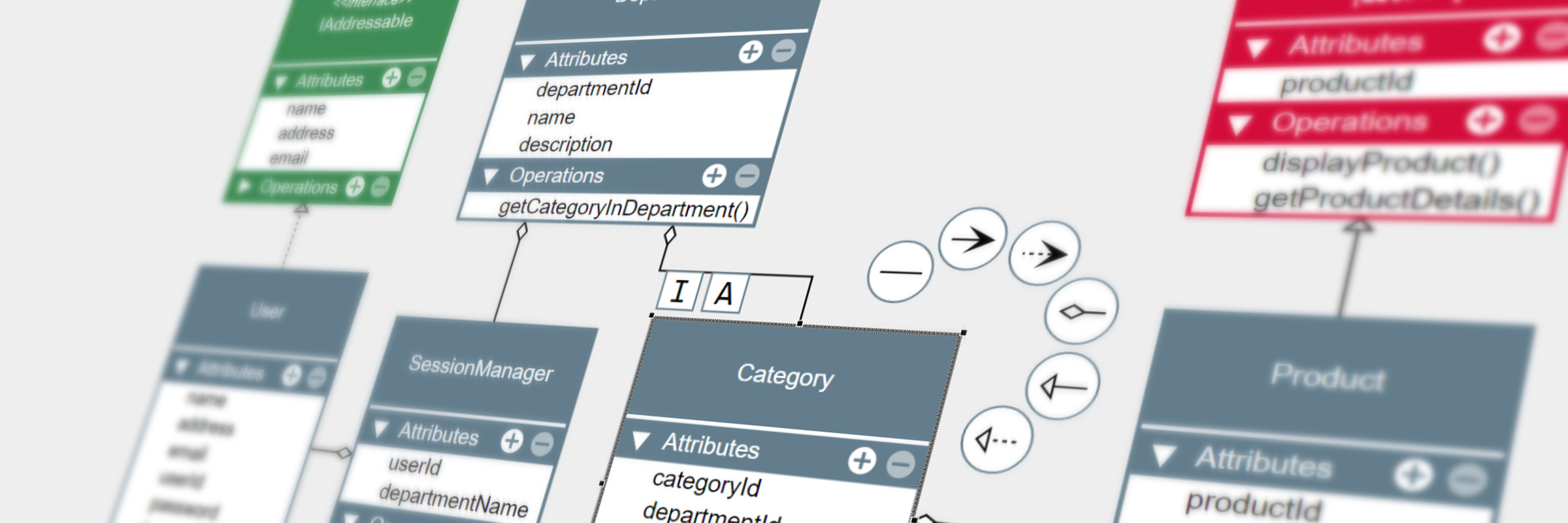
A UML class diagram is a structural description of a software system, at the level of its class implementation. Hopefully, clearly showing the properties and methods of each class. This representation provides a quick overview of the class and helps to identify common fields or methods that may be abstracted in a parent class or interface.

Furthermore, inheritance is depicted as relationships between the class entities in the form of differently styled connections.

These basic elements are sufficient to formalize a software architecture in a concise diagram that can be used as a reference during software development.
Challenges of UML Diagram Visualizations
Aside from class diagrams, UML encompasses various other types of diagrams that document diverse aspects of software systems. For instance:
-
Activity diagrams illustrating individual workflows
-
Sequence diagrams depicting interactions over a time sequence
Despite their differences, these diagrams share a common goal:
-
Representing interconnected elements within the system
The basic elements of a class diagram are the class entities with an arbitrary amount of stacked labels for the name of the class with its methods and properties and the connections that support different dash styles and arrows.
Depending on the interactivity of the visualization, additional elements might be required to add or remove fields or collapse different sections on the class entities.
Another aspect that is even more important for the readability is the layout of class entities and the paths of the relations. The dependency chain defines a structural order on the classes and interfaces and should be reflected in the graphical representation.
To avoid confusion in the diagram, it’s advisable to minimize crossings of relationship paths and group similar types of relationships together.
Trying to include all these aspects manually is extremely time consuming and frequently results in suboptimal diagrams, which at their worst, can be more perplexing than enlightening.
Mastering UML Diagram Visualizations with yFiles
A detailed graphical representation needs to address all aspects of UML diagram visualization. It should be adaptable to the varying needs of the UML diagram rendering and creation.
yFiles is a commercial programming library explicitly designed for diagram visualization and is thus an ideal fit for addressing the complexities of UML diagram visualization. Its extensive customization options enable nearly limitless possibilities for visually representing UML diagram elements and accommodating interactive user input. The sophisticated layout algorithms of yFiles automatically arrange the entities in a concise and clear diagram, continuously adapting to any changes you make.
Consider the journey of JetBrains, a leading provider of integrated development environments (IDEs), facing the challenge of visualizing complex codebases within their software. By embracing yFiles for UML diagramming, they transformed their IDEs into dynamic platforms where developers could effortlessly grasp intricate code structures. Through tailored customization options, JetBrains crafted visually captivating diagrams, bridging the gap between technical intricacies and intuitive understanding.
This empowered both seasoned developers and newcomers to navigate through code complexities with ease, enhancing productivity and fostering collaboration across their development teams.

How to make a simple UML diagram?
Diagrams can be created from an existing code base, or interactively with intuitive keyboard, mouse, and touch gestures. The yFiles generic I/O mechanism allows you to store and create diagrams using formats that are most suitable for the specific use case, such as JSON.
UML Diagram Editor Example
The UML Diagram Editor Sample Application that comes with yFiles for HTML implements these advanced features and clearly demonstrates how it addresses the various challenges encountered in UML class diagram visualization.
Interactive Class Entities
This application uses SVG styles to visualize the class entities which render the name, attributes, and methods. The built-in mechanism to place and render labels stacks the labels easily and automatically clips the text with an optional ellipsis.
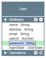
Any click on a class entity is forwarded to the style implementation, enabling listening for clicks on interactive elements, e.g. to collapse the attributes or methods section, to select single labels on the class, or to add new entries or remove them.

The class entities also support label editing.
Double-clicking a label on the class entity opens up an input field to edit that label.
Context-sensitive Interactions
Diagram editors frequently suffer from cluttered and convoluted user interfaces. In contrast, this example strives to eliminate unnecessary elements and instead employs context-sensitive interactions, aiding users in focusing on specific tasks.
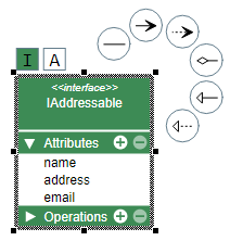
While yFiles for HTML does include built-in support for creating new connections, in this application, it has been customized to display a connection context menu upon selecting a class entity.

This customized context menu, designed for a streamlined user interface, offers an intuitive method for users to create new connections. Additionally, in the web application, another enhancement is that newly created connections automatically generate a new class entity if the gesture concludes on the empty canvas.
The context menu can also be used to adjust the class entity itself.
In this example, it is used to switch between different entity types, i.e. class, interface, or abstract.
UML Diagram Example Source Code
With yFiles, you can create a UML diagram on your favorite platform.
yFiles for HTML, yFiles WPF, yFiles.NET, and yFiles for Java (Swing) included is a UML Diagram Editor Sample Application that demonstrates tailored visualizations for the nodes and connections, and a customized UI that simplifies working with the diagrams.
The source code of the UML Diagram Editor Sample Application is part of these yFiles packages and available on the yWorks GitHub repository:
Implement Your Own UML Diagram Editor
Test the yFiles diagramming library with a fully functional trial package.
Feel free to explore and test the capabilities of the yFiles diagramming library with our fully functional trial package.
To implement your own UML diagram editor, select the UML Diagram Editor Sample Application that is part of this yFiles package.
The application serves not only as a showcase but also offers best-practices source code that you can utilize in your own projects.
yFiles makes it easy to customize all aspects of this application, for example you can include your own styling, change the user interaction, or load data from your own data sources.
Have a quick look and also interact with the yFiles UML diagram demo!
Features like the node visualizations and the specialized automatic layout are separate components that work in any yFiles-based project.
STEP BY STEP GUIDE:
-
Download the trial version of yFiles for your target platform at the yWorks Customer Center.
-
Navigate to the source directory of the UML Diagram Editor Sample Application.
-
Explore the sample application’s features and
-
adjust its source code to match your requirements or
-
copy the source code of the features you like to your own project.
-
Conclusion
In summary, a UML diagram provides a standardized way to visually represent software systems, enhancing communication and understanding within development teams. Leveraging tools like yFiles simplifies the creation of premium UML diagrams.
By downloading the yFiles evaluation package or exploring the yFiles UML diagram demo, you can get a taste of how easy it is to create stunning, highly customized and crystal clear UML Diagrams.
Overall, designing a UML diagram with yFiles facilitates better collaboration and navigation through complex software projects, resulting in more successful outcomes.
